| Cím: | Solutions to the problems of the Eötvös Competition of 2002 | ||
| Szerző(k): | Gyula Radnai | ||
| Füzet: | 2003/októberi melléklet, 54 - 62. oldal |  PDF | MathML PDF | MathML |
|
| Témakör(ök): | Eötvös Loránd (korábban Károly Irén) | ||
|
A szöveg csak Firefox böngészőben jelenik meg helyesen. Használja a fenti PDF file-ra mutató link-et a letöltésre. 1. We want to estimate the force exerted on the arms of a gymnast at the lowest point if he swings from a handstand into a great circle. Apply the following simple model: Fix a homogeneous metal rod of length and mass at the end of a very long rope of constant length, and release it from its position shown in Figure 1.. Calculate what force is exerted on the rope at the instant shown in Figure 1.. (The mass of the rope is negligible.) 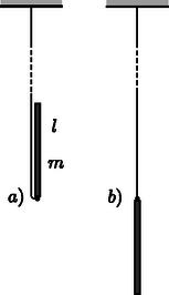 Figure 1 Solution. There are two forces acting on the tumbling rod: the gravitational force and force exerted by the rope (Figure 2). Both are vertical (the variable magnitude force of the rope is also vertical, because the rope is ``very long''). Since there are only vertical forces acting on the rod, its mass center can move only along a vertical line, so its motion will be vertical (non-harmonic) oscillating motion. 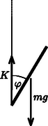 Figure 2 The vertical displacement of the end of the rod which is fixed to the rope is zero throughout the motion so it will not accelerate vertically. In the state in question, the velocity of the mass center is zero, its acceleration is at maximum and its magnitude equals with the acceleration of the endpoints of the rod in the frame of reference of the mass center: 2. Though it is not asked in the phrasing of the problem, it can be useful to calculate the force acting on the rope in any position of the rod while including an angle with the vertical direction. With similar calculations (work theorem + Newton's second law) the result is: 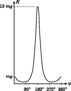 Figure 3 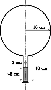 Figure 4 After this we make the flask rotate around its vertical axis in such a way that it turns three times per second. We make sure that the temperature stays constant everywhere along the wall of the flask. After a sufficiently long time a state of equilibrium is reached. Make a schematic drawing representing the position of the water inside the flask. The surface of a uniformly rotating liquid is a paraboloid of rotation in the homogeneous gravitational field of the Earth. The vertical cross-section of this is shown in Figure 5. The equation of the ``rotated parabola'' in the coordinate system depicted in the figure is 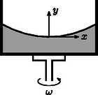 Figure 5 Examining the actual data in the problem, it can easily be seen that the surface of the rotating liquid takes the form of a paraboloid of rotation without the edge of the liquid reaching up to the sphere. However, one question may arise ‐ and it was the clue to the correct solution ‐ whether if we continue the surface of the paraboloid beyond the neck would it cut into the sphere or not? If it did, there could be water also in the sphere under the paraboloid of rotation. Take again the vertical cross-section, which contains the axis of rotation. Determine the lowest point of the parabola osculating with the circle, which is the cross-section of the sphere. Let the depth of this point compared to the center of the circle be . Then the equation of the parabola (take the center of the circle as the origin of the coordinate system) is: 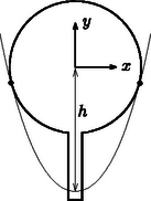 Figure 6 When the parabola and the circle osculate (Figure 6.), the above equation can have only one root and therefore the discriminant must be zero and this gives the condition for This means that the paraboloid osculating with the sphere goes half a centimeter above the lowest point of the neck of the flask turned upside-down. However, the paraboloid which gives the solution of the problem is somewhat above this in a way that the amount of water in the neck under the paraboloid is less than the original quantity by the same amount as the amount which is in a narrow band in the sphere under the paraboloid. But how did the water get there? Some of the contestants thought when the flask was being accelerated the water could have spattered there. This assumption clearly shows that students have interesting experiences with the stirring equipment in the school laboratories. This is not the solution of course, but that the evaporating water from the neck precipitates in a certain place on the wall of the flask. The driving force of this thermodynamical process inside the flask is the tiny pressure gradient mutually caused by the rotation and the earth's gravitational field. Looking from a rotating frame of reference the water is in equilibrium along a paraboloid of rotation, because this is the condition that determines the shape of the surface. Comparing different paraboloids of rotation, on the higher surfaces the energy of the water is higher than on lower ones. In a state of equilibrium the water surface must be the same paraboloid both in the neck and in the sphere. If it were not so, the evaporation-precipitation process would find the state of smaller overall energy. Consequently, the draft shown in Figure 7 is the correct solution (with a proper explanation). 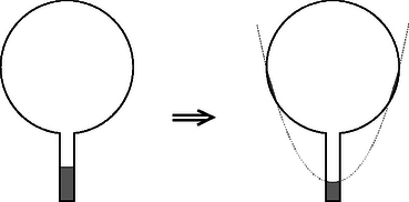 Figure 7 Notes. 1. The determination of the exact position of the paraboloid was not expected here, since it can hardly be done with the mathematics learned in the secondary school. 2. Bence Béky, a contestant from Budapest found out how there could be water on the wall of the flask, but he doesn't think it can really happen. As he writes: ``This does not happen similarly to the fact that water in a glass does not climb out on the table however small an energy level could be there''. The interesting thing is that it can climb out even in perfect thermal equilibrium and just because of that small air pressure difference that is between the surface of the water in the glass and the table (or rather the floor). Covering the glass of water standing on a table with a bell jar this experiment can be carried out. It might take a while though. (Without the bell jar the water will also ``climb out'' of the glass, but because of the big space in the room it won't precipitate anywhere, so it stays in the air as unsaturated vapour.) What force do the two bodies exert on each other? Does the result change if the radius of one hemisphere is decreased to half of its original? 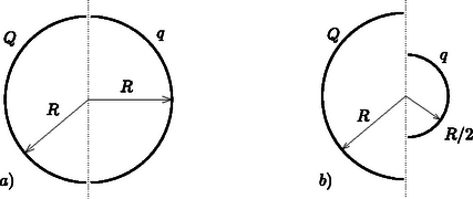 Figure 8 Solution. ``If you can't solve a problem, make an easier one of it for yourself.'' is the advice of György Pólya (1888‐1985) in his book of ``How to solve it''. Let us try to do the same until we get a problem we can solve. From there if we reconsider the chain of thoughts that lead us to the solution we could find ideas leading to the solution of more difficult problems. Let us first deal with question . What would be the case if the electric charge on both of the hemispheric shells were equal ? What would be the case if the charges were of opposite sign ? Here, the plane capacitor comes to mind. On the plates of a plane capacitor charged up to charge there are charges and , and there is a homogeneous electric field between them. The energy of the capacitor is Let us start stepping back from here. If the charges on the plates are not and , but and , then the difference is that they don't attract but rather repel each other. is now the magnitude of the electric field strength at the outer side of the plates. The electric field of two uniformly charged shells of charges placed facing each other is the same as the field outside of a single sphere charged up to . The field strength in this case outside the sphere equals the electric field strength deriving from a point charge placed in the middle of the sphere The charge density on the surface of the sphere is: The energy density (energy content of the unit volume, a pressure-like quantity) on the surface of the sphere is: We have calculated the force acting between the two hemispheric shells of electric charge each that are placed facing each other. Let us now get back to the original question , which differs from the one we discussed above only in that the electric charge on one of the shells is not but instead. The electrostatic force is proportional to the charge of the body, therefore Remark. As can be seen we have derived a very similar formula to Coulomb's law, only the numeric coefficient differing from the known formula. We could even find the places where the point charges and should be placed to exert the same force on each other, but this was not an objective of the problem. The points in question do not coincide with the mass centers of the homogeneous mass density hemispheric shells, as it was stated falsely by some contestants. The reason for the difference is that only the effect of the homogeneous gravitational field can be substituted by a force acting in the mass center, and the Coulomb field here is inhomogeneous! To answer question , remember again the advice of György Pólya. In the problem there is an asymmetric arrangement, so let us first try a symmetric one that is presumably easier to handle. Add to arrangement its mirror image (Figure 9). 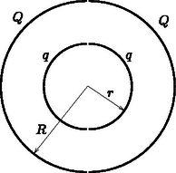 Figure 9 Write down the forces acting between the two left side hemispherical shells and the two right side hemispherical shells. It can be expressed as a sum of four forces To calculate let us consider the electric field generated by two concentric spherical shells, the inner with radius and of charge , and the outer with radius and charge . This is practically the electric field generated by the four hemispheric shells. 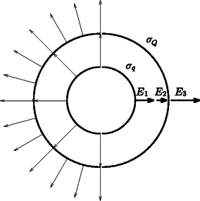 Figure 10 Inside the smaller spherical shell (Figure 10.) the electric field strength is zero. The charge density on the surface is Using the solution for question 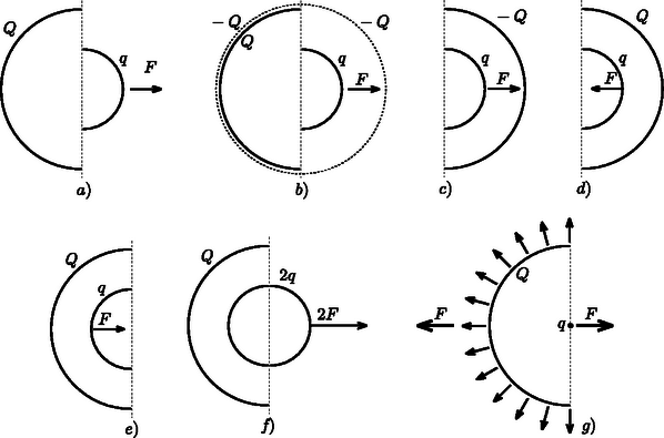 Figure 11 Now we only have to utilize the action-reaction principle: a sphere of charge (the electric field of which can be substituted with the field of a point charge outside of the sphere, which means it is independent of ) exerts the same force on a hemispheric shell of charge as the force we are looking for (Figure 11.g). The final result can be found by applying Coulomb's law and the gas pressure analogy. 2. Endre Csóka (Debrecen) got even further in the generalization of the problem. He ‐ with a reflection method similar to the previous one ‐ showed that the force acting between the hemispheric shells is the same as expressed above even if the axes of symmetry of the two shells include an arbitrary angle with each other. The magnitude of the force apart from the product of the charges is dependent on the radius of the larger hemispheric shell only. Its direction is parallel with the axis of symmetry of the larger hemisphere though in general its line of action does not pass through the common center of the hemispherical shells (Figure 12.a). This result is also surprising, because if and are about the same, and there is only a tiny difference between them, the direction of the force changes abruptly depending on which radius is larger (Figures 12.b and 12.c). 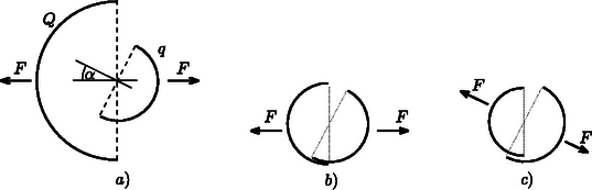 Figure 12 |